| PM5 Series: Wireless Relay Pack
The Pelican Power Control Module (PM5)
The Pelican Power Control Module (PM5)
| PM5 Series: Wireless Relay Pack
The Pelican Power Control Module (PM5)
| PM5 Series: Wireless Relay Pack
| Flexible, On/Off Control
Lights, exhaust fans, pumps, valves, and more - our wireless relay pack gives you the ability to enable and disable equipment right from your the Pelican App.
DESIGN
Easy Installation
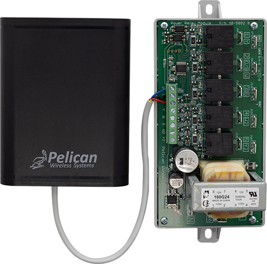
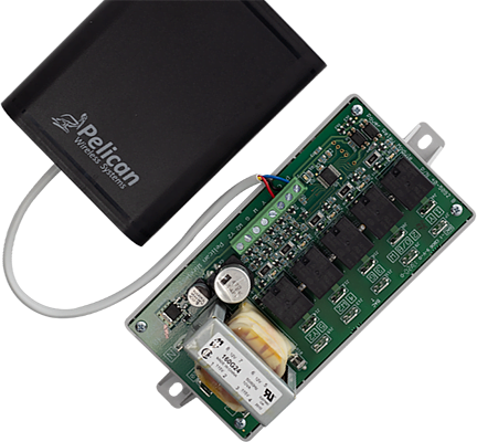
A Pelican PM5 is composed of two parts, the line voltage relay pack installed at the equipment or in the panel that has the circuitry you are turning on and offs. And the 3-wire connected low voltage antenna that gets installed where it can easily connect to your Pelican wireless network.
MANAGEMENT
LOGIC CONTROL
Schedule specific times to run or turn off systems. Set auto-adjusting schedules to match Dusk and Dawn in your area. Or link the PM5 to your Pelican thermostats so systems start when the thermostats need them too.
WEB-APP CONNECTED
Virtual
Right from the Pelican App you can view if systems are on or off, enable/disable relays in real-time, set schedules, and view historical data.

| Flexible, On/Off Control
Lights, exhaust fans, pumps, valves, and more - our wireless relay pack gives you the ability to enable and disable equipment right from your the Pelican App.
DESIGN
Easy Installation
A Pelican PM5 is composed of two parts, the line voltage relay pack installed at the equipment or in the panel that has the circuitry you are turning on and offs. And the 3-wire connected low voltage antenna that gets installed where it can easily connect to your Pelican wireless network.
WEB-APP CONNECTED
Virtual
Right from the Pelican App you can view if systems are on or off, enable/disable relays in real-time, set schedules, and view historical data.
MANAGEMENT
LOGIC CONTROL
Schedule specific times to run or turn off systems. Set auto-adjusting schedules to match Dusk and Dawn in your area. Or link the PM5 to your Pelican thermostats so systems start when the thermostats need them too.
| Flexible, On/Off Control
Lights, exhaust fans, pumps, valves, and more - our wireless relay pack gives you the ability to enable and disable equipment right from your the Pelican App.
DESIGN
Easy Installation
A Pelican PM5 is composed of two parts, the line voltage relay pack installed at the equipment or in the panel that has the circuitry you are turning on and offs. And the 3-wire connected low voltage antenna that gets installed where it can easily connect to your Pelican wireless network.
MANAGEMENT
LOGIC CONTROL
Schedule specific times to run or turn off systems. Set auto-adjusting schedules to match Dusk and Dawn in your area. Or link the PM5 to your Pelican thermostats so systems start when the thermostats need them too.
WEB-APP CONNECTED
Virtual
Right from the Pelican App you can view if systems are on or off, enable/disable relays in real-time, set schedules, and view historical data.
| 3-Wire connection.
The Power Control Module's antenna can be mounted inside the building where it can easily connect to your Pelican wireless network. It then communicates with the Power Relay Module over a 3-wire low-voltage connection.

| 3-Wire connection.
The Power Control Module's antenna can be mounted inside the building where it can easily connect to your Pelican wireless network. It then communicates with the Power Relay Module over a 3-wire low-voltage connection.
| 3-Wire connection.
The Power Control Module's antenna can be mounted inside the building where it can easily connect to your Pelican wireless network. It then communicates with the Power Relay Module over a 3-wire low-voltage connection.
| Common Applications
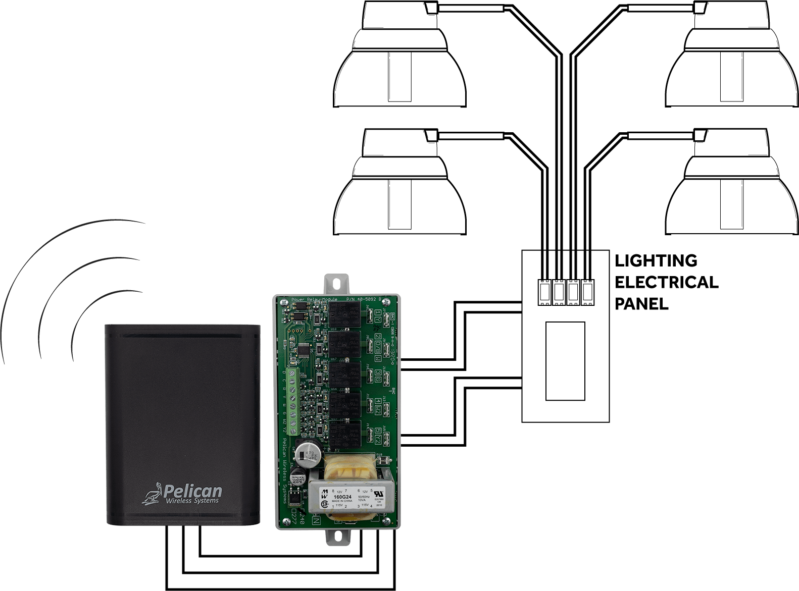
Outside Light Control
The PM5 can be used to turn On and Off main lighting circuits based on occupied/unoccupied schedules.
The PM5 can be used to turn On and Off main lighting circuits in relation to when the sun sets and rises in your area.
A third-party momentary contact switch can be wired to the PM5 to provide temporary override periods. The amount of time the circuit will be active, after the momentary contact switch is pressed, its adjustable.
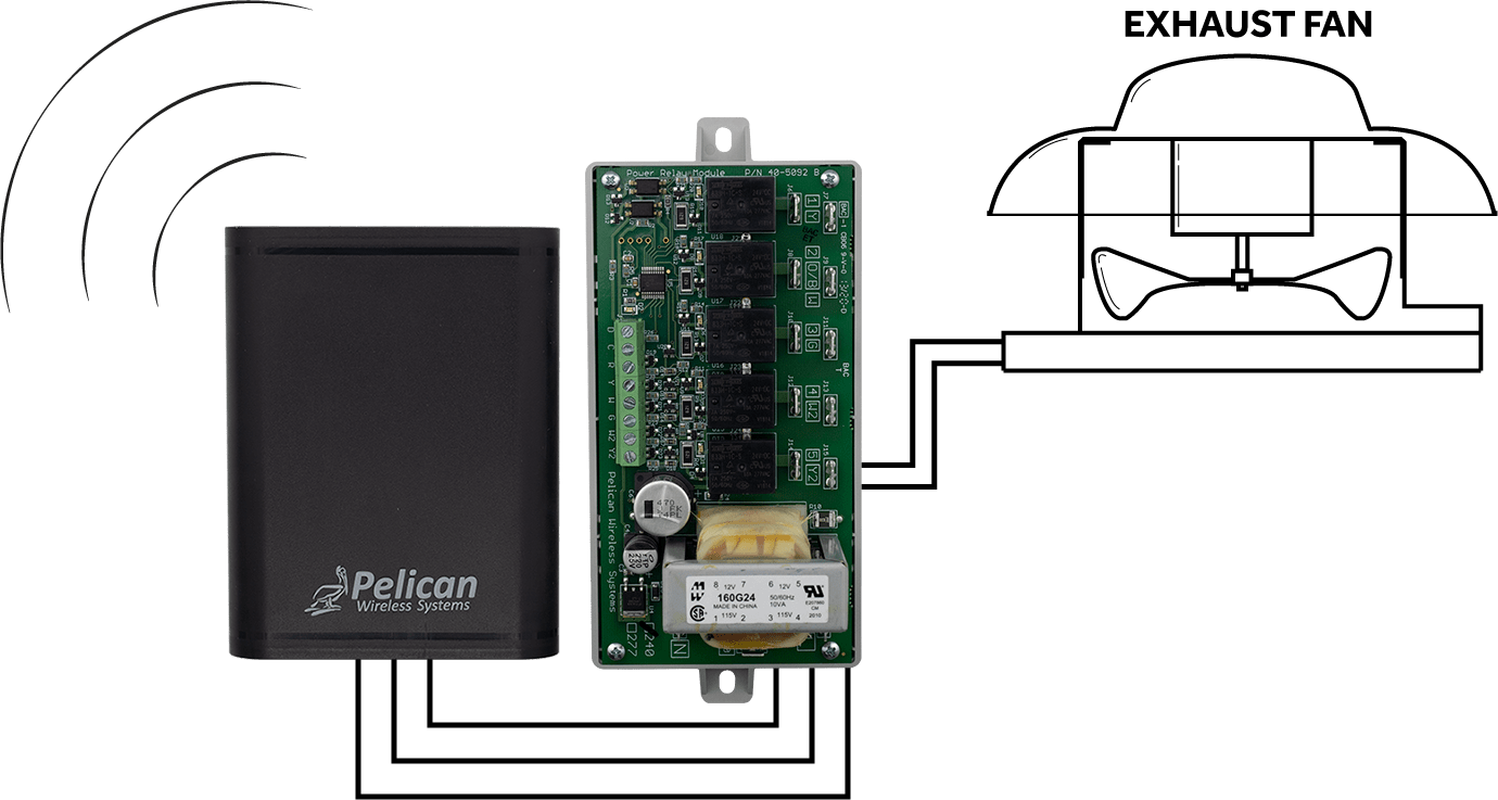
Exhaust Fan Management
The PM5 can be used to start/stop an exhaust fan based on occupied/unoccupied schedules.
In some applications, your exhaust fan only need to run when one or more of your Pelican thermostats need it to. Pelican can interlock your thermostats fan, heating, and cooling demands to specific relays on the PM5. This way when one or more thermostats need the exhaust fan to run, they will send their request over your Pelican wireless network directly to the selected PM5 and the exhaust fan will be enabled.
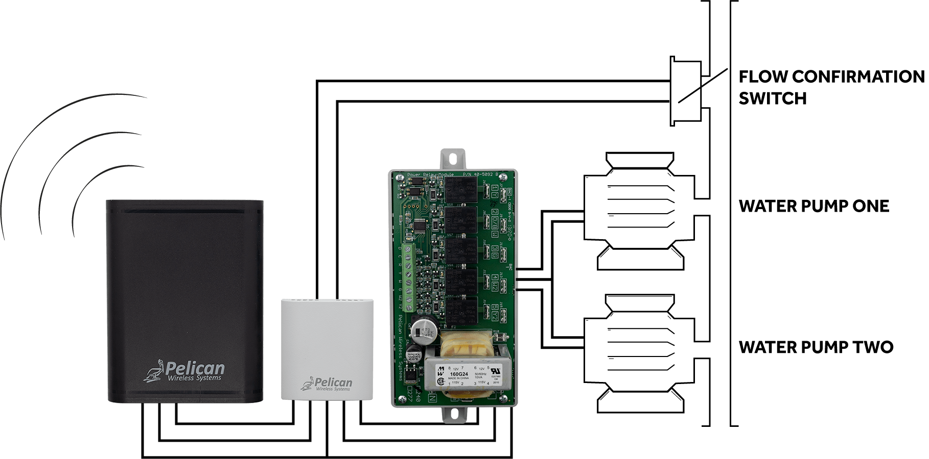
Lead/Lag Pump Control with Feedback
The PM5 can be used to start/stop a pump based on occupied/unoccupied schedules and/or interlocked with Pelican thermostat demands. Add an optional Pelican TA1* to your PM5 and it can be used to verify water flow. If no water flow is detected, an alarm is generated by the Pelican EMS.
*Pelican TA1 sold separately.
For sites with multiple pumps, the PM5 provides full rotation logic for up to five (5) pumps. The auto-rotation logic starts the pump with the lowest run-time and then automatically switches to the next pump on a pre-defined hourly run-time schedule. This rotation logic can be set to start/stop based on occupied/unoccupied schedules and/or interlocked with Pelican thermostat demands. Add a Pelican TA1* to your PM5 and it can be used to verify water flow. If no water flow is detected, an alarm is generated by the Pelican EMS and the PM5 will automatically try to generate flow by starting the next pump.
*Pelican TA1 sold separately.
In some applications, your pumps only need to run when one or more of your Pelican thermostats need it to. Pelican can interlock your thermostats heating and cooling demands to specific relays on the PM5. This way when one or more thermostats need a pump to run, they will send their request over your Pelican wireless network directly to the selected PM5 and the pump at your water plant will start.
Once the pump is enabled, it will remain active until all thermostats have eliminated the need for that pump. Pelican will keep the pump running for an additional (and adjustable) “hold-off” timer; just incase another thermostat needs the pump in a few minutes. Once the hold-off timer ends, the pump will stop running until one or more thermostats request it to run again.
In some applications, the pumps need to be running before a Pelican thermostats can start its heating or cooling cycle, such as in water-source heat pump systems. In this application, Pelican can interlock thermostats to request a pump to be active and wait until it receives water flow verification before enabling heating or cooling. The communication between Pelican thermostats and the PM5 if over the Pelican wireless network.
*For flow verification, a Pelican TA1 needs to be wired to the PM5. TA1 is sold separately.
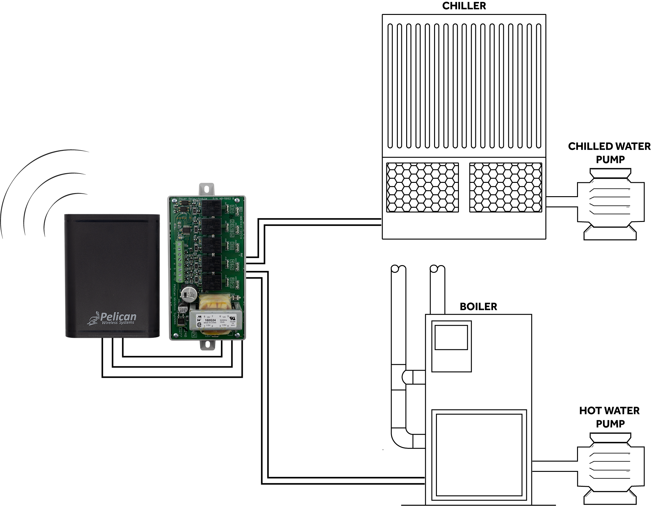
HVAC Plant Enable
The PM5 can be used to start/stop a boiler based on occupied/unoccupied schedules and/or interlocked with Pelican thermostat demands.
The PM5 can be used to start/stop a chiller based on occupied/unoccupied schedules and/or interlocked with Pelican thermostat demands.
In some applications, your boiler and or chiller only need to run when one or more of your Pelican thermostats need it to. Pelican can interlock your thermostats heating and cooling demands to specific relays on the PM5. This way when one or more thermostats need the boiler or chiller to run, they will send their request over your Pelican wireless network directly to the selected PM5 and the needed equipment at your water plant will start.
Once the equipment is enabled, it will remain active until all thermostats have eliminated the need for that equipment. Pelican will keep the equipment running for an additional (and adjustable) “hold-off” timer; just incase another thermostat needs the equipment in a few minutes. Once the hold-off timer ends, the equipment will stop running until one or more thermostats request it to run again.
| Common Applications
Outside Light Control
The PM5 can be used to turn On and Off main lighting circuits based on occupied/unoccupied schedules.
The PM5 can be used to turn On and Off main lighting circuits in relation to when the sun sets and rises in your area.
A third-party momentary contact switch can be wired to the PM5 to provide temporary override periods. The amount of time the circuit will be active, after the momentary contact switch is pressed, its adjustable.
Exhaust Fan Management
The PM5 can be used to start/stop an exhaust fan based on occupied/unoccupied schedules.
In some applications, your exhaust fan only need to run when one or more of your Pelican thermostats need it to. Pelican can interlock your thermostats fan, heating, and cooling demands to specific relays on the PM5. This way when one or more thermostats need the exhaust fan to run, they will send their request over your Pelican wireless network directly to the selected PM5 and the exhaust fan will be enabled.
Lead/Lag Pump Control with Feedback
The PM5 can be used to start/stop a pump based on occupied/unoccupied schedules and/or interlocked with Pelican thermostat demands. Add an optional Pelican TA1* to your PM5 and it can be used to verify water flow. If no water flow is detected, an alarm is generated by the Pelican EMS.
For sites with multiple pumps, the PM5 provides full rotation logic for up to five (5) pumps. The auto-rotation logic starts the pump with the lowest run-time and then automatically switches to the next pump on a pre-defined hourly run-time schedule. This rotation logic can be set to start/stop based on occupied/unoccupied schedules and/or interlocked with Pelican thermostat demands. Add a Pelican TA1* to your PM5 and it can be used to verify water flow. If no water flow is detected, an alarm is generated by the Pelican EMS and the PM5 will automatically try to generate flow by starting the next pump.
In some applications, your pumps only need to run when one or more of your Pelican thermostats need it to. Pelican can interlock your thermostats heating and cooling demands to specific relays on the PM5. This way when one or more thermostats need a pump to run, they will send their request over your Pelican wireless network directly to the selected PM5 and the pump at your water plant will start.
Once the pump is enabled, it will remain active until all thermostats have eliminated the need for that pump. Pelican will keep the pump running for an additional (and adjustable) “hold-off” timer; just incase another thermostat needs the pump in a few minutes. Once the hold-off timer ends, the pump will stop running until one or more thermostats request it to run again.
In some applications, the pumps need to be running before a Pelican thermostats can start its heating or cooling cycle, such as in water-source heat pump systems. In this application, Pelican can interlock thermostats to request a pump to be active and wait until it receives water flow verification before enabling heating or cooling. The communication between Pelican thermostats and the PM5 if over the Pelican wireless network.
Once the pump is enabled, it will remain active until all thermostats have eliminated the need for that pump. Pelican will keep the pump running for an additional (and adjustable) “hold-off” timer; just incase another thermostat needs the pump in a few minutes. Once the hold-off timer ends, the pump will stop running until one or more thermostats request it to run again.
HVAC Plant Enable
The PM5 can be used to start/stop a boiler based on occupied/unoccupied schedules and/or interlocked with Pelican thermostat demands.
The PM5 can be used to start/stop a chiller based on occupied/unoccupied schedules and/or interlocked with Pelican thermostat demands.
In some applications, your boiler and or chiller only need to run when one or more of your Pelican thermostats need it to. Pelican can interlock your thermostats heating and cooling demands to specific relays on the PM5. This way when one or more thermostats need the boiler or chiller to run, they will send their request over your Pelican wireless network directly to the selected PM5 and the needed equipment at your water plant will start.
Once the equipment is enabled, it will remain active until all thermostats have eliminated the need for that equipment. Pelican will keep the equipment running for an additional (and adjustable) “hold-off” timer; just incase another thermostat needs the equipment in a few minutes. Once the hold-off timer ends, the equipment will stop running until one or more thermostats request it to run again.
Once the pump is enabled, it will remain active until all thermostats have eliminated the need for that pump. Pelican will keep the pump running for an additional (and adjustable) “hold-off” timer; just incase another thermostat needs the pump in a few minutes. Once the hold-off timer ends, the pump will stop running until one or more thermostats request it to run again.
| Common Applications
Outside Light Control
The PM5 can be used to turn On and Off main lighting circuits based on occupied/unoccupied schedules.
The PM5 can be used to turn On and Off main lighting circuits in relation to when the sun sets and rises in your area.
A third-party momentary contact switch can be wired to the PM5 to provide temporary override periods. The amount of time the circuit will be active, after the momentary contact switch is pressed, its adjustable.
Exhaust Fan Management
The PM5 can be used to start/stop an exhaust fan based on occupied/unoccupied schedules.
In some applications, your exhaust fan only need to run when one or more of your Pelican thermostats need it to. Pelican can interlock your thermostats fan, heating, and cooling demands to specific relays on the PM5. This way when one or more thermostats need the exhaust fan to run, they will send their request over your Pelican wireless network directly to the selected PM5 and the exhaust fan will be enabled.
Lead/Lag Pump Control with Feedback
The PM5 can be used to start/stop a pump based on occupied/unoccupied schedules and/or interlocked with Pelican thermostat demands. Add an optional Pelican TA1* to your PM5 and it can be used to verify water flow. If no water flow is detected, an alarm is generated by the Pelican EMS.
*Pelican TA1 sold separately.
For sites with multiple pumps, the PM5 provides full rotation logic for up to five (5) pumps. The auto-rotation logic starts the pump with the lowest run-time and then automatically switches to the next pump on a pre-defined hourly run-time schedule. This rotation logic can be set to start/stop based on occupied/unoccupied schedules and/or interlocked with Pelican thermostat demands. Add a Pelican TA1* to your PM5 and it can be used to verify water flow. If no water flow is detected, an alarm is generated by the Pelican EMS and the PM5 will automatically try to generate flow by starting the next pump.
*Pelican TA1 sold separately.
In some applications, your pumps only need to run when one or more of your Pelican thermostats need it to. Pelican can interlock your thermostats heating and cooling demands to specific relays on the PM5. This way when one or more thermostats need a pump to run, they will send their request over your Pelican wireless network directly to the selected PM5 and the pump at your water plant will start.
Once the pump is enabled, it will remain active until all thermostats have eliminated the need for that pump. Pelican will keep the pump running for an additional (and adjustable) “hold-off” timer; just incase another thermostat needs the pump in a few minutes. Once the hold-off timer ends, the pump will stop running until one or more thermostats request it to run again.
In some applications, the pumps need to be running before a Pelican thermostats can start its heating or cooling cycle, such as in water-source heat pump systems. In this application, Pelican can interlock thermostats to request a pump to be active and wait until it receives water flow verification before enabling heating or cooling. The communication between Pelican thermostats and the PM5 if over the Pelican wireless network.
Once the pump is enabled, it will remain active until all thermostats have eliminated the need for that pump. Pelican will keep the pump running for an additional (and adjustable) “hold-off” timer; just incase another thermostat needs the pump in a few minutes. Once the hold-off timer ends, the pump will stop running until one or more thermostats request it to run again.
*For flow verification, a Pelican TA1 needs to be wired to the PM5. TA1 is sold separately.
HVAC Plant Enable
The PM5 can be used to start/stop a boiler based on occupied/unoccupied schedules and/or interlocked with Pelican thermostat demands.
The PM5 can be used to start/stop a chiller based on occupied/unoccupied schedules and/or interlocked with Pelican thermostat demands.
In some applications, your boiler and or chiller only need to run when one or more of your Pelican thermostats need it to. Pelican can interlock your thermostats heating and cooling demands to specific relays on the PM5. This way when one or more thermostats need the boiler or chiller to run, they will send their request over your Pelican wireless network directly to the selected PM5 and the needed equipment at your water plant will start.
Once the equipment is enabled, it will remain active until all thermostats have eliminated the need for that equipment. Pelican will keep the equipment running for an additional (and adjustable) “hold-off” timer; just incase another thermostat needs the equipment in a few minutes. Once the hold-off timer ends, the equipment will stop running until one or more thermostats request it to run again.

| Web-App enabled control.
Right from the Pelican App you can manage all aspects of the Pelican Power Control Module: schedules on/off periods, set vacation schedules, manage event schedules, view historical data, and more.